![]() Home
Home
![]() Products
Products
![]()
![]() IASopen
IASopen
![]()
![]()
![]() IASopen Modules
IASopen Modules
![]()
![]()
![]()
![]() Configurations
Configurations
![]()
![]()
![]()
![]() Type declarations
Type declarations
![]()
![]()
![]()
![]() Program organization...
Program organization...
![]()
![]()
![]()
![]() Data bases
Data bases
![]()
![]()
![]()
![]() Data loggings
Data loggings
![]()
![]()
![]()
![]() Alarm loggings
Alarm loggings
![]()
![]()
![]()
![]() Message loggings
Message loggings
![]()
![]()
![]()
![]() Recipes
Recipes
![]()
![]()
![]()
![]() Visualizations
Visualizations
![]()
![]()
![]()
![]() Reports
Reports
![]()
![]()
![]()
![]() User managements
User managements
![]()
![]()
![]()
![]() Language managements
Language managements
![]()
![]()
![]() Version informations
Version informations
![]()
![]()
![]()
![]() Build 850 - Build 800
Build 850 - Build 800
![]()
![]()
![]()
![]() Build 800 - Build 750
Build 800 - Build 750
![]()
![]()
![]()
![]() Build 750 - Build 700
Build 750 - Build 700
![]()
![]()
![]()
![]() Build 700 - Build 650
Build 700 - Build 650
![]()
![]()
![]()
![]() Build 650 - Build 600
Build 650 - Build 600
![]()
![]()
![]()
![]() Build 600 - Build 550
Build 600 - Build 550
![]()
![]()
![]()
![]() Build 550 - Build 500
Build 550 - Build 500
![]()
![]()
![]()
![]() Build 500 - Build 450
Build 500 - Build 450
![]()
![]()
![]()
![]() Build 450 - Build 400
Build 450 - Build 400
![]()
![]()
![]() Download
Download
![]()
![]()
![]() Hardware requirements
Hardware requirements
![]()
![]()
![]() Software requirements
Software requirements
![]()
![]()
![]() Scope of delivery
Scope of delivery
![]()
![]()
![]() Training
Training
![]()
![]() Project engineering
Project engineering
![]() Company
Company
![]() Contact
Contact
![]() Imprint
Imprint
![]() Privacy policy
Privacy policy
Configurations
General
An integral part of the configuration is called the device configuration or even IO-Configuration. Using different devices or bus systems in a project is simply possible, E.g. PROFIBUS-DP and CANopen. The coupling of different bus systems or devices (gateway functionality) is also possible.
The connection between the process data of a device to the global data base is made by the declaration of global variables with direct addresses (I/OAdressen).
The Declaration of multiple resources in accordance with IEC 61131-3 is possible within a configuration. Within a resource is the instantiation of programmes according to IEC 61131-3 and the assignment of tasks to programs. The Declaration by tasks controlling program is carried out in accordance with IEC 61131-3. There are cyclical tasks, periodic tasks and event-driven tasks available. The multiple instance of a program Declaration is just as possible as parameter passing to programs.
The communication between different configurations can be done via network variables.
IO-Configuration
An integral part of the configuration is called the device configuration or even IO configuration.
The IO configuration is done graphically and with property dialogs
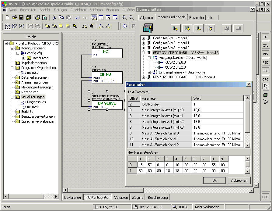
Usually, no additional external software is required to the bus configuration.
Supported Bus systems
The interconnection of devices within a bus system is done via connections graphically.
The configuration of the devices are on the basis of electronic data sheets or device configuration files, E.g. EDS files (electronic data sheet) for CANopen, GSD files (device master file) with PROFIBUS-DP and EtherCAT XML files.
At the time, following bus systems (industrial Ethernet and fieldbus systems classic) are supported (this list will be constantly expanded):
|
|
|
|
|
|
|
|
|
|
|
|
|
|


Planned or ongoing implementation is the support of the following bus systems:
|
|
|
|

Device classes
Each device is assigned to one due to its connectivity within a configuration (network) of five device classes.
The following device classes are available:
![]() Controller
class: The controller is the control computer, usually a PC. Always
just one controller exists per configuration. When working locally with
several computers, a configuration is for each computer to create. The
communication between the controllers can be done through so-called traffic
or network variable communication devices.
Controller
class: The controller is the control computer, usually a PC. Always
just one controller exists per configuration. When working locally with
several computers, a configuration is for each computer to create. The
communication between the controllers can be done through so-called traffic
or network variable communication devices.
![]() Master
class: Master devices are connected directly to the control computer
(e.g. via a serial interface) or inside of the controller (e.g. fieldbus
master connections or AD converter plug-in cards) as a plug-in card.
Master
class: Master devices are connected directly to the control computer
(e.g. via a serial interface) or inside of the controller (e.g. fieldbus
master connections or AD converter plug-in cards) as a plug-in card.
![]() Slave-class:
Slave class appliances are on a bus (usually a field bus) connected. Can
be connected directly to a controller, you needed a master's degree (field
bus connection). In contrast to subsequent bus coupler class appliances,
no other a - output devices can be connected to devices of the slave class.
Slave-class:
Slave class appliances are on a bus (usually a field bus) connected. Can
be connected directly to a controller, you needed a master's degree (field
bus connection). In contrast to subsequent bus coupler class appliances,
no other a - output devices can be connected to devices of the slave class.
![]() Bus
coupler class: A bus coupler is a device on a bus (usually a field
bus) is connected. He can be connected directly to the controller, but
this requires a master's degree (field bus connection). Possibly more
bus coupler and so-called a - output devices can be connected to the bus
coupler.
Bus
coupler class: A bus coupler is a device on a bus (usually a field
bus) is connected. He can be connected directly to the controller, but
this requires a master's degree (field bus connection). Possibly more
bus coupler and so-called a - output devices can be connected to the bus
coupler.
![]() Input/output
device class: Input / output devices can be directly connected
to a controller or master, but be integrated into the network via bus
coupler
Input/output
device class: Input / output devices can be directly connected
to a controller or master, but be integrated into the network via bus
coupler
Supported Devices
Following groups of devices are currently supported:
Controller (device class controller)
Fieldbus-Master-Connections (device class master)
Fieldbus-Slave-Connections (device class master)
Network-Protocols (device class master)
PLC-Protocols (device class master)
Serial Protocols (device class master)
IO-Cards (device class master)
OPC and DDE (device class master)
Other Master devices (device class master)
Feldbus-Slave-Geräte (device class slave)
Buskoppler (device class bus couplerr)
Ein-/Ausgabemodule (device class input/output device)
Device selection and device connection
The insertion of a device using a selection dialog:
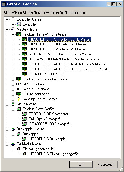
Devices are graphically linked via lines.
Diener
automation GmbH & Co. KG
Kapellenweg 21
D-51580 Reichshof
Phone
+49 (0)2265 / 99745-0
Fax
+49 (0)2265 / 99745-20
E-Mail
info@diener-automation.de